Standard Seal Designs
Standard seal designs, shown in the table below, are best for rough bore finishes or for materials with high coefficient of thermal expansion.
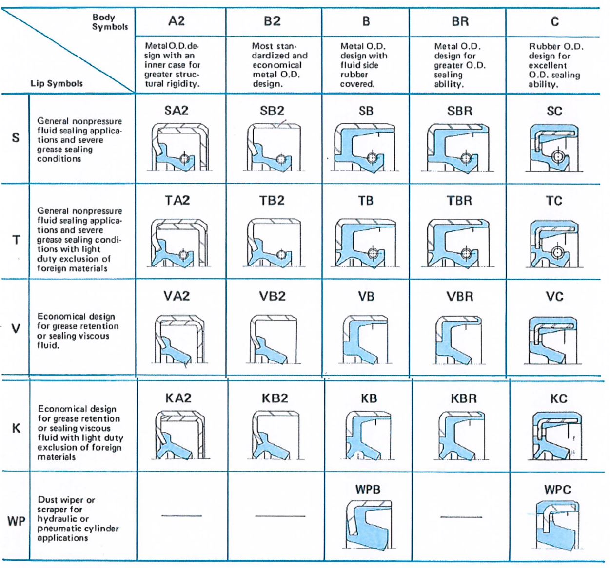
Table Notes:
Metal O.D. seals are most suitable for steel or cast iron housing materials.
Rubber covered O.D. seals are preferred for soft alloy or plastic housing materials. They are also suitable for steel or cast iron housing materials.
Selecting a Standard Seal Design
Comparing Lip Designs
I. “S” and “T” Lip Designs
The table below illustrates “S” and “T” lip symbols for general non-pressure applications. The “S” design is a single lip oil seal with a garter spring to provide consistent radial load against the shaft. The “T” design is a single lip oil seal with an auxiliary dust lip to provide effective light duty dust exclusion.
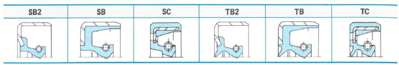
The table below shows approximate limits of the “S” and “T” oil seal lip designs.
| Shaft Diameter | Nitrile Lip Maximum Continuous Shaft Speed¹ | Maximum Continuous Pressure² | Maximum Total Eccentricity³ |
| General | 3,500 rpm | 5 psi | .020″ |
| .500 | 8,000 rpm | 5 psi | .004″ |
| 1,000 | 7,000 rpm | 5 psi | .006″ |
| 2,000 | 4,500 rpm | 5 psi | .010″ |
| 3,000 | 3,800 rpm | 5 psi | .013″ |
| 4,000 | 2,750 rpm | 5 psi | .017″ |
¹ Higher shaft speeds are possible using high temperature materials
² Higher continuous pressures are possible for shaft speeds below 200 ft/min
³ Higher eccentricity is possible if shaft speed is reduced
II. “V” and “K” Lip Designs
The table below illustrates “V” and “K” oil seal designs. The “V” design is a single lip oil seal. The “K” design is a single lip oil seal with an auxiliary lip for light dust exclusion. These are low cost seals designed primarily for retention of grease and similar viscous fluids.
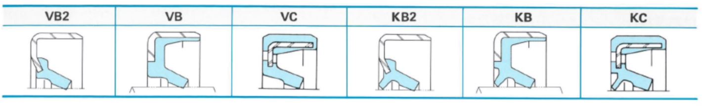
The table below shows approximate limits of the “V” and “K” oil seal lip designs.
| Shaft Diameter | Maximum Shaft Speed | Maximum Continuous Pressure | Maximum Total Eccentricity¹ |
| General | 2,000 rpm | 4 psi | .005″ |
| .500 | 4,000 rpm | 4 psi | .003″ |
| 1,000 | 3,000 rpm | 4 psi | .005″ |
| 2,000 | 2,300 rpm | 4 psi | .006″ |
| 3,000 | 1,700 rpm | 4 psi | .008″ |
| 4,000 | 1,400 rpm | 4 psi | .010″ |
¹ Higher eccentricity is possible if maximum shaft speed is reduced
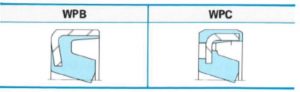
III. “WP” Lip Designs
The table below illustrates “WP” oil seal designs. The “WP” were designed as dust wipers (or, scrapers) for reciprocating applications such as hydraulic cylinder rods.
The operating limits for the “WP” design are only slightly different from the “V” and “K” designs:
- Maximum shaft motion is linear velocity of 200 ft./min. (1M/sec.)
- Maximum pressure capability is 4 psi (.28Kg/cm²).
- Stroke length should be limited to 78 inches (1.98 m) maximum.
- Eccentricity considerations involve only shaft-to-bore misalignment. Maximum allowable is ±0.004 inch (0.1 mm).
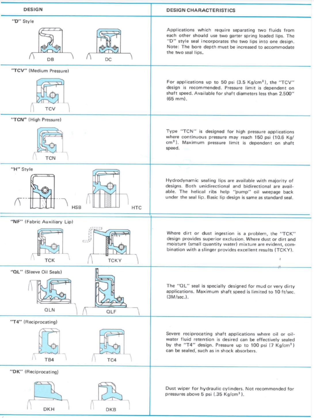
Nonstandard Seal Designs
Nonstandard seal designs, shown in the table below, are best for special applications that cannot be satisfied by standard designs.
I. Lip Material Selection
The tables below provide comparisons for popular lip materials; however other elastomers – such as PTFE and Ethylene Acrylate – are available.
| Base Polymer | Nitrile | Polyacrylate | Silicone | Fluoroelastomer |
| Material Code | A | T | S | F |
| Temperature Range | -50°F ~ 250°F -45°C ~ 120°C |
-20°F ~ 300°F -30°C ~ 150°C |
-80°F ~ 400°F -60°C ~ 200°C |
-30°F ~ 400°F -35°C ~ 200°C |
| Oil Resistance | ◎ | ◎ | ◍ | ◎ |
| Acid Resistance | ◍ | △ | △ | ◎ |
| Alkali Resistance | ◍ | X | X | △ |
| Water Resistance | ◍ | △ | ◍ | ◍ |
| Heat Resistance | ◍ | ◎ | ◎ | ◎ |
| Cold Resistance | ◍ | △ | ◎ | △ |
| Wear Resistance | ◎ | ◎ | ◍ | ◎ |
| Ozone Resistance | ◍ | ◎ | ◎ | ◎ |
Key:
◎ Very good
◍ Good for most applications
△ Fair, can be used if no other materials are available
X Not good
| Advantages: | Disadvantages: | |
| NITRILE |
|
|
| POLYACRYLATE |
|
|
| SILICONE |
|
|
| FLUOROELASTOMER |
|
|
| Lip Material | |||||
| Type of Fluid | Nitrile | Polyacrylate | Silicone | Fluoroelastomer | |
| Engine Oil | SAE 30 Wt. | ◎ | ◎ | ◎ | ◎ |
|---|---|---|---|---|---|
| SAE 10 Wt. | ◎ | ◎ | ◍ | ◎ | |
| Gear Oil | Super Gear | ◎ | ◎ | △ | ◎ |
| Hypoid Gear | ◍ | ◍ | X | ◎ | |
| Turbine Oil No. 2 | ◍ | ◍ | ◍ | ◎ | |
| Machine Oil No. 2 | ◍ | ◍ | △ | ◎ | |
| Automatic Transmission Fluid | ◎ | ◎ | △ | ◎ | |
| Petroleum Base Lubricating Oil | ◎ | ◎ | △ | ◎ | |
| Gasoline | △ | X | X | ◎ | |
| Light Oil/Kerosene | △ | X | X | ◍ | |
| Cutting Oil | ◎ | ◍ | △ | ◎ | |
| Grease | ◎ | ◎ | ◎ | ◎ | |
| E.P. Lubricants | ◍ | ◎ | X | ◎ | |
| Water-Glycol | ◎ | X | ◍ | ◍ | |
| Alcohol | ◎ | X | ◍ | △ | |
| 20% Hydrochloric Acid Solution | △ | △ | △ | ◎ | |
| 30% Sulfuric Acid Solution | △ | △ | X | ◎ | |
Key:
◎ Very good
◍ Good for most applications
△ Fair, can be used if no other materials are available
X Not good
II. Metal Case & Spring Material Selection
The tables below lists material specifications uses for the metal case and garter spring components.
| Case | |
| SAE NO. | APPLICATION |
| 1008 ~ 1010 | General |
| 30302 ~ 30304 | Special Corrosion Resistance Condition |
| Spring | |
| SAE NO. | APPLICATION |
| 1070 ~ 1080 | General |
| 30302 ~ 30304 | Special Corrosion Resistance Condition |
For general oil or grease applications, metal cases are typically produced from carbon steel. For special applications, such as when sealing sea water, corrosive fluids or gases, metal cases are typically produced from stainless steel.
For general applications, the garter springs are typically made of piano wire. For special applications, such as when corrosion or extreme heat resistance are required, garter springs are typically made of stainless steel.
Shaft Recommendations
Seal and shaft compatibility is dependent on four conditions:
- shaft tolerance
- lead chamfer
- finish
- hardness
Shaft Tolerance
The table below shows recommended shaft tolerances for general applications. Shaft tolerance range should be decreased for high speed or high pressure applications.
| Diameter Inch | Tolerance | Diameter Metric | Tolerance |
| Up to 4.000″ | ±.003 | Up to 100 mm | ±0.08 |
| 4.001″ to 6.000″ | ±.004 | 100.10 to 150.00 | ±0.10 |
| 6.001″ to 10.000″ | ±.005 | 150.10 to 250.00 | ±0.13 |
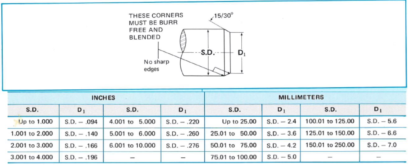
Shaft Chamfer
Shaft chamfer assists in the installation process. Without a proper chamfer, the seal lip may be damaged or distorted, resulting in a dislodged garter spring. The table below shows recommended shaft chamfer.
Shaft Finish
The shaft surface roughness greatly influences the amount of lip wear. Recommended roughness is:
Rotating 10 to 20 µ inch AA (.25µM to .50 µM AA)
Reciprocating 5 to 10 µ inch AA (.13µM to .25 µM AA)
Shaft Hardness
Shaft hardness prevents excessive wear, deformation, scratches and nicks. It also allows for easy machining for proper roughness. Under normal conditions, the seal contact area of the shaft should be Rockwell C45 minimum.
Housing Recommendations
- Steel and cast iron provide good surfaces for both rubber covered and metal O.D. seals.
- For soft alloy bores, rubber covered O.S. seals provide better sealing capability. Metal O.D. seals occasionally back out of the bore due to thermal expansion of the soft alloy.
- If plastic is used, rubber O.D. seals are recommended.
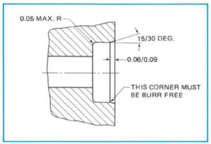
Bore Chamfer
A bore chamfer assists in the installation of the seal. Below is the recommended configuration for the chamfer. Proper chamfer angle and depth minimizes cocking or lack of squareness of the seal to the shaft and distortion of the seal case. It also reduces assembly force.
Surface Roughness
Extremely rough bore finishes may allow paths for fluid to leak between seal O.D. and bore. The table below shows recommended maximum housing bore roughness.
| Metal O.D. | Rubber O.D. | |
| Maximum Roughness |
100µ inch AA | 2.50µM AA |
|---|---|---|
| 150µ inch AA | 3.75µM AA |
Bore Diameter Tolerance
The tables below shows recommended housing bore diameter, bore tolerance and nominal pressfit.
Inch Sizes
| Bore Diameter | Bore Tolerance | Nominal Pressfit | O.D. Tolerance¹ | Out of Round² | |||
|---|---|---|---|---|---|---|---|
| Seals with Metal O.D. | Seals with Rubber O.D. | Seals with Metal O.D. | Seals with Rubber O.D. | Seals with Metal O.D. | Seals with Rubber O.D. | ||
| Up to 1.000 | ±.001 | .004 | .006 | ±.002 | ±.003 | .005 | .010 |
| 1.001 – 2.000 | ±.001 | .004 | .006 | ±.002 | ±.003 | .006 | .012 |
| 2.001 – 3.000 | ±.001 | .004 | .006 | ±.002 | ±.003 | .006 | .014 |
| 3.001 – 4.000 | ±.0015 | .005 | .008 | ±.002 | ±.004 | .007 | .018 |
| 4.001 – 6.000 | ±.0015 | .005 | .010 | +.003 -.002 |
±.004 | .009 | .023 |
| 6.001 – 8.000 | ±.002 | .006 | +.003 -.002 |
.012 | |||
| 8.001 – 9.000 | ±.002 | .007 | +.004 -.002 |
.015 | |||
| 9.001 – 10.000 | ±.002 | .008 | +.003 -.002 |
.015 | |||
¹ The Seal O.D. is the average of a minimum three measurements to be taken at equally spaced positions.
² The Out of Round is the maximum variance between any of the readings used in determining Seal O.D.
Equivalent Metric Sizes
| Bore Diameter | Bore Tolerance | Nominal Pressfit | O.D. Tolerance¹ | Out of Round² | |||
|---|---|---|---|---|---|---|---|
| Seals with Metal O.D. | Seals with Rubber O.D. | Seals with Metal O.D. | Seals with Rubber O.D. | Seals with Metal O.D. | Seals with Rubber O.D. | ||
| Up to 25.00 | ±0.025 | 0.10 | 0.15 | ±0.05 | ±0.08 | 0.13 | 0.25 |
| 25.01 – 50.00 | ±0.025 | 0.10 | 0.15 | ±0.05 | ±0.08 | 0.15 | 0.30 |
| 50.01 – 75.00 | ±0.025 | 0.10 | 0.15 | ±0.05 | ±0.08 | 0.15 | 0.36 |
| 75.01 – 100.00 | ±0.038 | 0.13 | 0.20 | ±0.05 | ±0.10 | 0.18 | 0.46 |
| 100.01 – 150.00 | ±0.038 | 0.13 | 0.25 | +0.08 -0.05 |
±0.10 | 0.23 | 0.58 |
| 150.01 – 200.00 | ±0.051 | 0.15 | +0.08 -0.05 |
0.30 | |||
| 200.01 – 225.00 | ±0.051 | 0.18 | +0.10 -0.05 |
0.38 | |||
| 225.01 – 250.00 | ±0.051 | 0.20 | +0.10 -0.05 |
0.38 | |||
¹ The Seal O.D. is the average of a minimum three measurements to be taken at equally spaced positions.
² The Out of Round is the maximum variance between any of the readings used in determining Seal O.D.